
Geosteering guide: the Lateral tab
Where each tool is and when to use it. Start with the horizontal-wells quick start; this guide assumes a lateral with a type well, an anchor and a few segments.
1. Key functions
- Section: TVDSS against vertical section (or MD), with the beds, the path and its log.
- Type log: the type well on the left (none yet: Set up type well, section 2). Its tops are the beds; the segment brackets sit beside it. Point at a bracket, or select a segment, to bring its trace forward and fade the others.
- Anchor: the top that ties the type well to the lateral's own pick. Bulk shift moves every bed up or down from there.
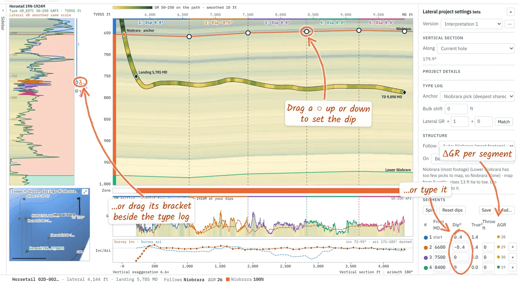
- Segments: each bends the beds by its dip along the section; a fault adds a throw.
- ΔGR: drilled minus modeled GR (RMS, API), per segment and for the lateral. Nothing moves unless you run Auto-fit.
- Inc/Azi strip: survey inclination (solid) and azimuth (dashed), with a dot at each station. While you point, its header and the status bar give both at the pointer (interpolated between stations); over the strip, the nearest station is ringed and its own readings are in the status bar. Inclination's scale reads at the left, azimuth's at the right; set either under Inc/Azi ▾.
- Survey sheet: Drilling → Survey sheet on the right-hand rail (or Surveys under the lateral in the project tree) opens every station: MD, inclination, azimuth, TVD, TVDSS, VS, N/S, E/W, closure, dogleg, build, turn, toolface, date and time with Δt and ft/hr, and the zone, depth below the anchor and in-target from your interpretation. Show All, the Lateral or Flagged stations: a likely missed station, an inclination or azimuth spike, a dogleg spike. Click a row to center the section on it; Copy pastes into a spreadsheet, Save CSV keeps it, Pop out opens it in its own window that follows the well. Type a station's time in the sheet; a survey file's date and time columns fill it.
- Comments: notes at a depth (bit trip, geosteering handover, mud pump down, downlink…), with an optional date and time. Right-click the wellbore → Add a comment here, or Comments in the toolbar. They show as boxes above the path; click one to edit. The same menu turns comments, survey dots and survey boxes on or off, and Save comments (CSV) writes MD, TVD, kind, text, date and time.
- Type log scales: two bars over the type log, as on a log header: the type well's GR and the lateral's, each with its left and right values. With a GR match, the lateral's bar reads in its own API (what lands at each edge).
- Strip scales: each log strip shows its top and bottom values at its left edge, in the curve's color, with a faint line at the middle. Click the name ▾ (e.g. GR ▾) for the scale: Auto, 0–150, 0–200, 50–250 or Custom.
- Project tree: the sidebar lists the laterals, type wells, grids and seismic, with Tops below. Each lateral opens to its Interpretations (+ starts one from scratch or duplicates one; right-click to mark one final, rename, compare or delete) its Logs (put one on the section or add it as a strip), its Surveys and its Comments. Click a type well to find it on the mini map, double-click it to use it; its eye shows or hides it behind the section (orange: shown; the tooltip says why). While the sidebar is hidden, the rail on the left edge opens it at any folder.
2. Set up a type well
A vertical with the top and base of your target picked. Its log and tops are the beds you steer through.
- Open the setup. No type well yet: Set up type well in the Lateral panel. Later: Type well list → Set up a type well…
- Choose a vertical. Nearest first, with its tops count and distance. Its washouts and bad density are flagged on import (Logs tab, Flags track). Not loaded? Open a LAS… No vertical at all? Use the lateral's build instead (a pseudo type log from the build section).
- Add 2 tops, top and base of the target, then Save tops:
- Type the MD. Where a surface maps that top, grid: 7,412 ft beside the row fills it in.
- Pick on log: click each top on the Logs tab; Done brings you back.
- Tops file…: CSV or Excel, rows matched by API or well name.
- Check. Each top shows ✓ or ⚠: below the log's TD (allowed, no log there), out of order with other wells, far from the surface, or in no other well.
- Use as type well, then set the Anchor: the top tied to the lateral's own pick (deepest shared pick by default).
Pick the target's top and base, not just one top. Two tops give the zone its thickness; a third or fourth (a marker above, the next bed below) helps when the bit leaves the zone.
3. Segments and dips
Each segment's number and dip sit along the top of the section, shortened or on two lines where the segment is narrow; point at one for the full label. Start a segment with right-click → Start a segment here, Shift-click, or Split and a click. Set its dip by dragging its ○ on the anchor bed, its bracket on the type log, or typing it. A plain drag keeps the next segment's far end in place; Shift-drag moves every bed beyond it. Drag a dashed segment start sideways to move it. Dragged dips stop at ±20°: a bigger step is usually a fault or a thickness change.
A segment's right-click menu (in the section, on its bracket or table row) types its dip, makes its start a fault, deletes it (it joins the segment before), hides it on the type log or shows only it. Reset dips returns to one segment at the structure dip from nearby wells.
Auto-fit
Select a segment → Auto-fit… (or the segment's right-click → Auto-fit segment N). It tries every dip near the grid and keeps the one whose modeled GR best matches the drilled GR.
- Match by: Shape + level (default: shape, with the GR leveled to the type log once from landing to TD), Shape only (loosest), or Value (API).
- Dip range: ±1 to ±10° around the grid (the followed structure, else the structure dip).
- Stay near grid: how hard an ambiguous match is pulled back to the grid.
- Throw at faults: also fits a fault's throw.
- Next segment: holds its end (as a drag does) or moves too.
A start, not an answer. Place the breaks yourself and fit one segment at a time. A dip at the range limit, or one that flips between Shape and Value, means the GR has too little character there.
Lump, don't split. Survey stations 90 ft apart can put 5–16 ft of error in TVD and make false dip "wrinkles". Fewer, longer segments are usually closer to the rock.
4. Faults
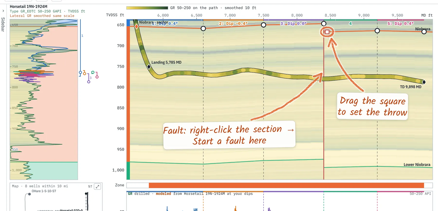
Right-click the section → Start a fault here, or right-click a segment start → make it a fault. Drag the square on the toe side to set the throw (+ is beds down on the toe side). Right-click the red plane for its angle (vertical, 75° or 60°), an exact throw, or to remove it. A repeated or missing section in the trace on the type log is the usual sign.
5. Thickening and thinning
The zone is thicker or thinner at the lateral than in the type well. Signs: the trace fits at the top of the zone but drifts at the base, or a dip drag stops at ±20°.
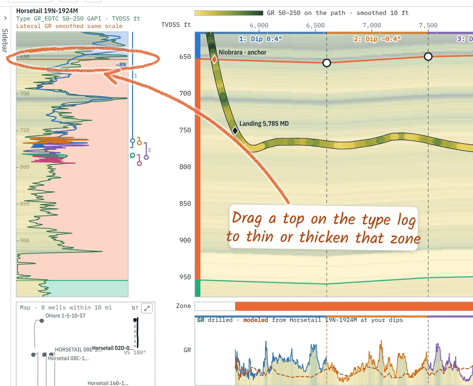
- Point at a top on the type log (not the anchor). The cursor turns to ↕ and the status bar names the zone a drag changes.
- Drag it away from the anchor to thicken the zone, toward it to thin. The anchor stays put; tops beyond move with it. The status bar gives the new %.
- Or type it: right-click the zone → thickness (% of type). Reset all zone thicknesses is in the same menu.
Changed zones show +8% or −8%; grey ticks mark the type well's own tops. Thickness is saved with the interpretation version and listed in the report and interpretation files.
One factor per zone, for the whole lateral. Where the zone thins along the hole, give the toe segments a closer type well (segment right-click → Segment N type well) or compare two with Compare TW.
6. Surfaces and structure
A surface is a structure grid of one top: depth to that top across the map. It shows on the map, as a dashed line in the section with its dip ahead of the bit, and on the logs.
Three kinds:
- Live from tops: gridded from every well's pick of a top; regrids as picks are added or moved.
- Loaded: ZMAP+, CPS-3 or XYZ from other software (Map tab → Grids and polygons → Load…).
- Snapshot: a dated, frozen copy of a surface, to compare the prognosis with what was drilled.
Make and show one:
- In the Lateral panel, Grids in the section → Add Mowry structure (or the top you follow), or turn on a top's eye under Grids in the project tree. It needs picks of that top in three or more wells.
- In the Lateral panel, Grids in the section lists each surface with its map dip over the next 500 ft past the bit (also in the status bar). Tick to show or hide.
- Compare the map dip with your last segment's dip before steering down dip.
Where surfaces show: the same show box is on the Map tab, the Lateral panel, the project tree's Grids folder and the Surfaces list on the Logs tab (show on the logs turns their dashed lines on the logs on or off).
Reading the line. It passes through every well's pick, this one's included; dotted where it runs past the wells. Lines → Tied at the bit moves each onto your interpreted bed there, to read the trend without the map's offset. Leave this well out shows what the map predicted before this well. Both are also on the section's right-click.
Beds that follow a surface. Structure → Follow in the Segments panel picks the top the beds follow (or off); your dips correct it. Past the heel and the toe the beds keep following the map along the section line, and past the map they carry on its trend, never going flat. A loaded surface of that top is followed first. The type well is drawn where it projects onto the section, at its own depths: if it sits off the line (the label gives how far), its tops can differ from the beds there by the map's dip over that distance.
Surfaces that grow with each well. When a lateral's interpretation is done, Mark as final (Version ⋯ menu, or right-click it in the tree). Right-click a top's grid → Add laterals with a final interpretation: each adds its top along the well, a point every 300 ft. Other versions never touch the surface; edits to the final one update it. Smoothing λ (0.001 with laterals; ⓘ on the Map tab) lets it miss points a little to stay smooth. Take a Snapshot first to keep the prognosis.
7. Target window
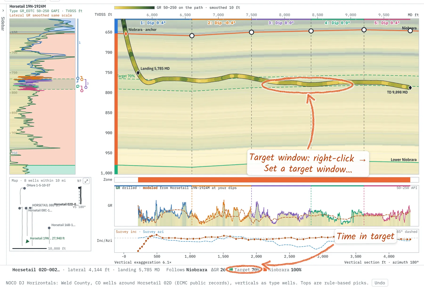
Right-click the type well → Set a target window…: a top and base bed, each with an offset (+ down). The green band follows the beds; the status bar, report and CSV give time in target and time in each zone.
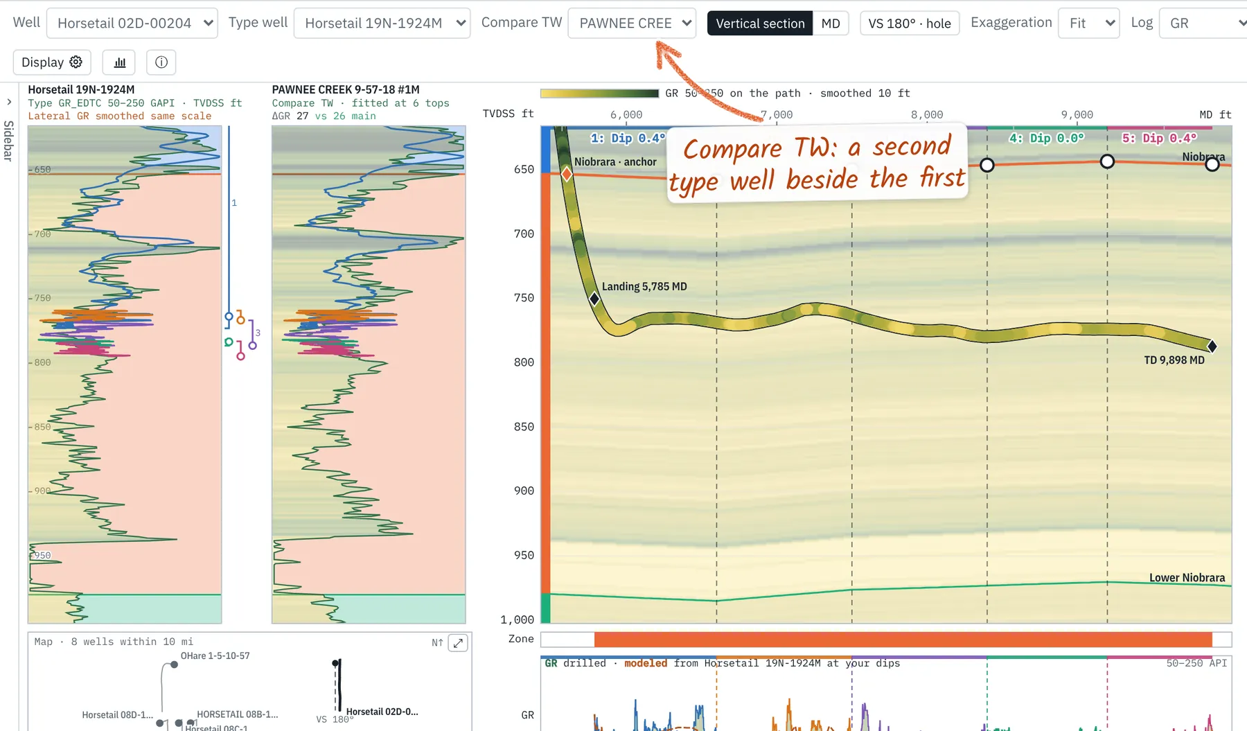
8. Multiple type wells and 2nd TW
2nd TW in the toolbar (also in the Type well panel) adds a second type well in its own column, fitted to the first one's tops, with ΔGR for each (green is the better predictor); right-click it to swap the two or use it for the selected segment. Any segment can take its own type well from its right-click menu → Segment N type well, so a change in thickness shows as a step at the segment start.
9. Map and gun barrel
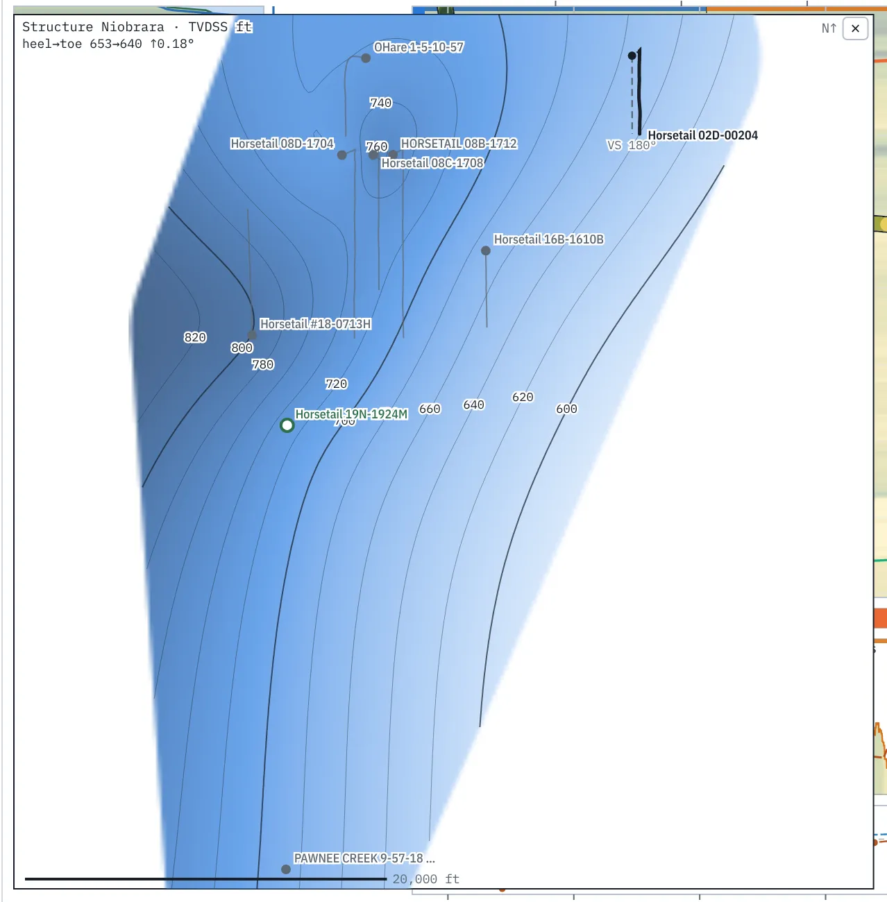
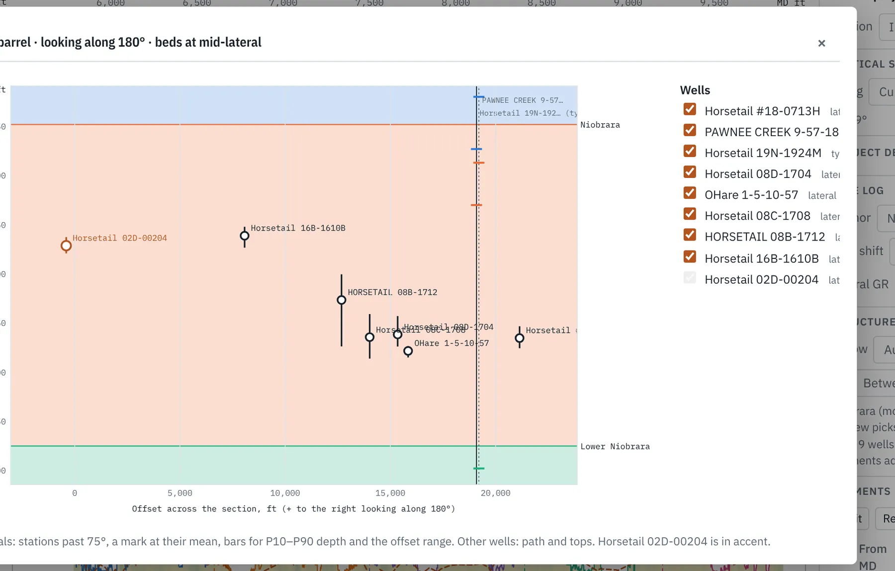
The small map under the type log shows the lateral, the type well and nearby wells over a grid made from every well's tops: structure (the depth to a top) or isopach (between two tops). Structure maps are hillshaded, in Batlow by default (Yellow-green-blue, Rainbow or Blues under the Map tab's Colors swatches, or right-click the map). The same palettes color the path and the GR fill in Display settings. Right-click the map → Grid, or click a grid in the project tree's Grids folder, to choose another top or interval, or use the Map tab's gridding, which the map can follow. Its contours are never closer than the Map tab's Contours every (20 by default) and widen as you zoom out; labels go on every fifth line. Its colors and scale match the Map tab. A dotted box marks the part of the section in view, and follows as you zoom and pan. Click a well to make it the type well; ⤢ opens the larger map. ZMAP+, CPS-3 and XYZ grids and lease polygons from other software load on the Map tab; their outlines show here and they list under Grids. Gun barrel looks along the lateral: each lateral as a mark at its mean depth and offset, with P10–P90 bars, beside the type well's tops. Right-click the section → Offset wells… draws wells near the section plane with their tops: verticals within 10 miles and horizontals within 1 mile by default, each settable from 250 ft to 20 miles.
10. Seismic
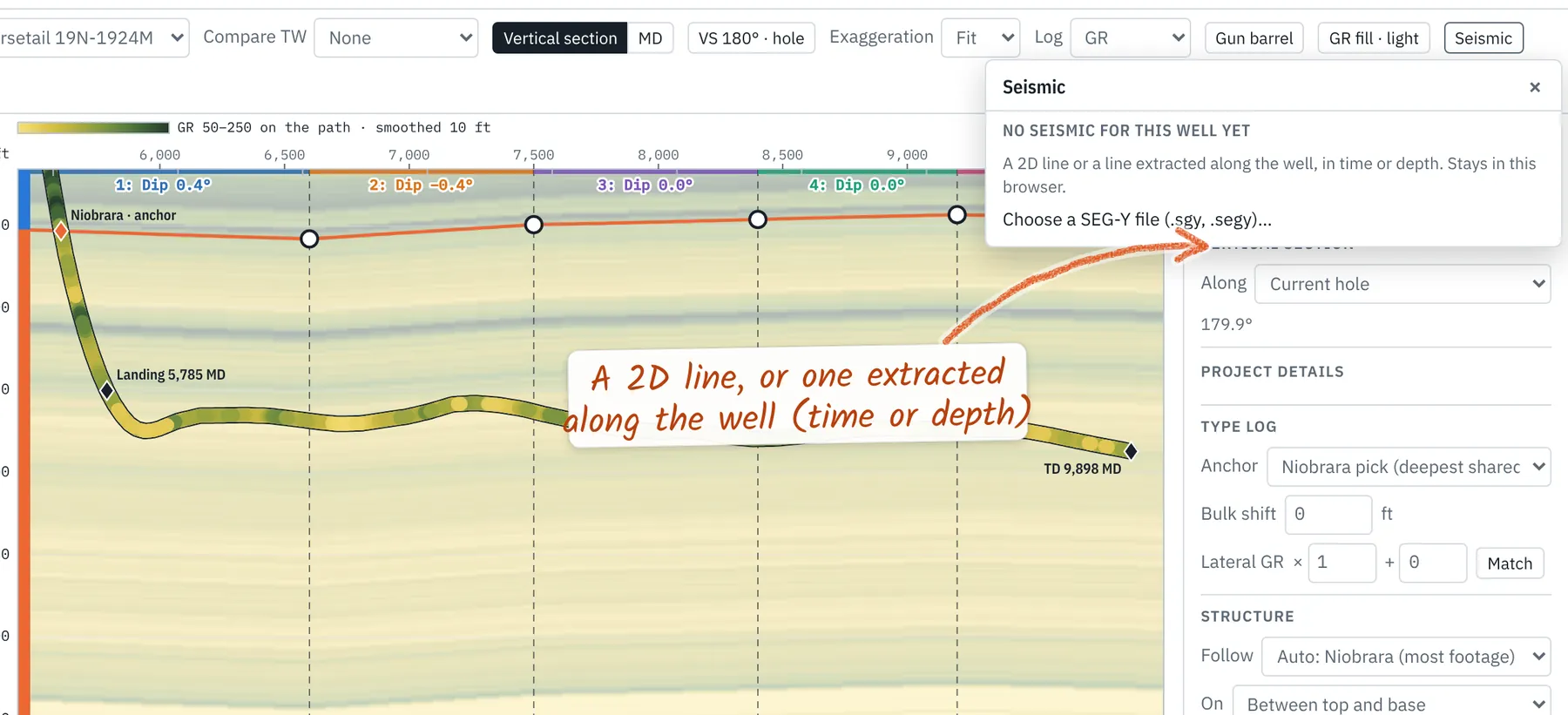
Seismic in the toolbar loads a SEG-Y line, a 2D line or one extracted along the well, and draws it behind the section. Set where its first and last traces fall and its time or depth scale; the placement is saved with the project.
11. Display settings
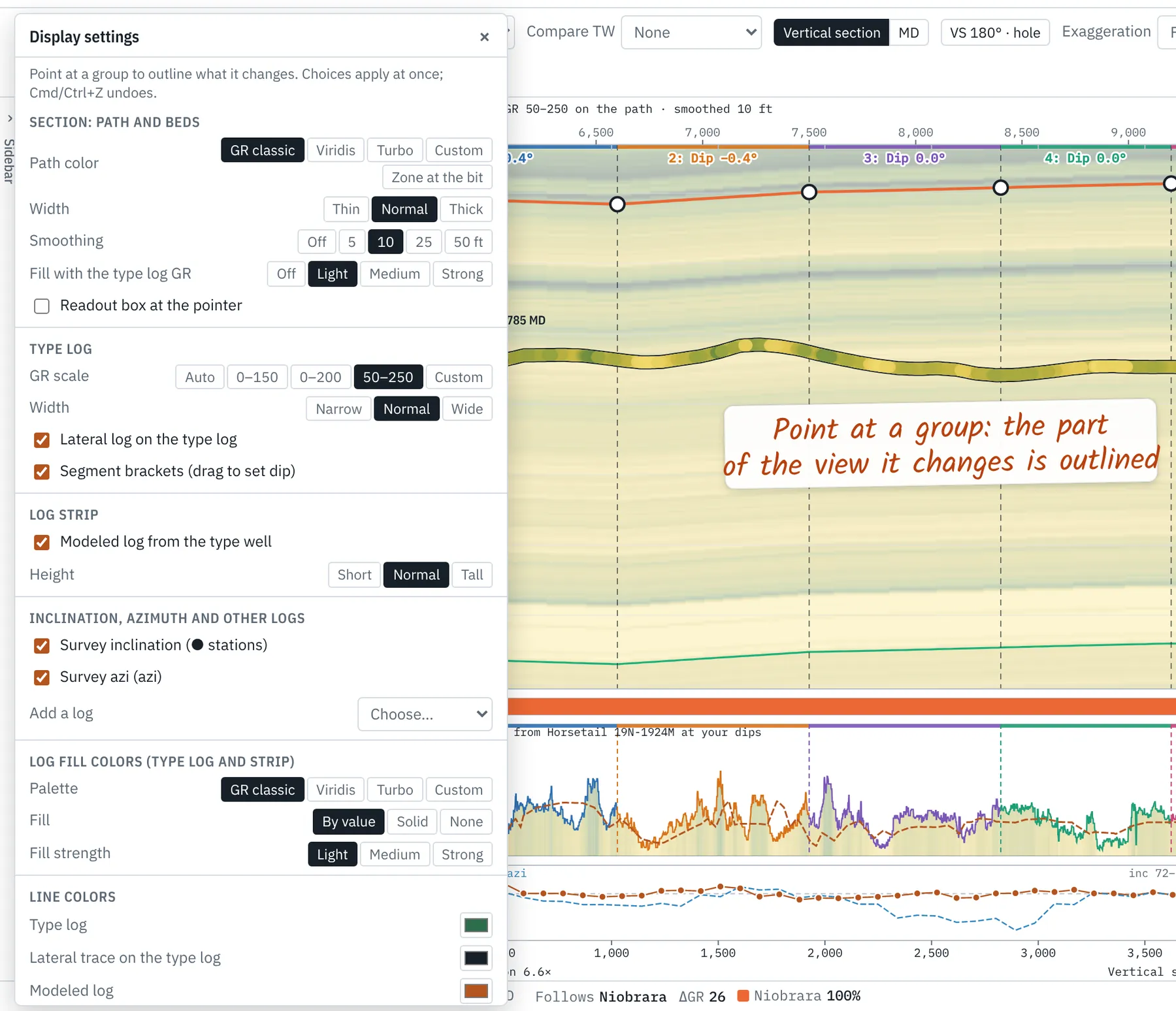
Display ⚙ (or Display settings… at the end of any right-click menu) sets path color (GR classic, Viridis, Turbo, custom, or the zone at the bit), scales, fills, smoothing and sizes; pointing at a group outlines what it changes. GR fill paints the section with the type log's GR, Exaggeration sets the vertical stretch, VS the section azimuth; Section on the right-hand rail holds both and the Log drawn on the path.
12. Interpretation versions and settings
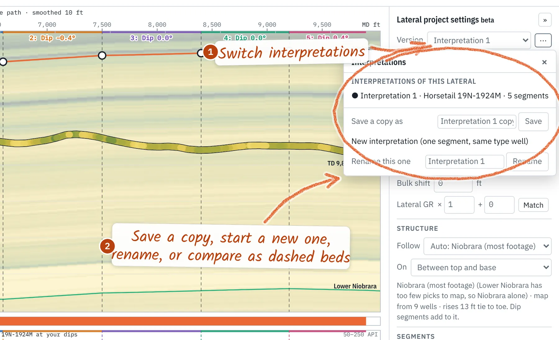
Version keeps several interpretations of one lateral, each with its own type well, anchor, dips, faults, thickness, target and GR match. ⋯ duplicates one, starts a new one from scratch, marks one final, renames, deletes, or compares one as dashed beds and a dashed modeled GR. In the project tree they sit under their lateral: click one to switch. The rail on the right opens one panel at a time: Segments, Type well, Section (vertical section azimuth), Steering, Drilling (runs, offsets, rig and dates) and Well info (operator, interpreter, notes for the report).
13. Stats and analysis
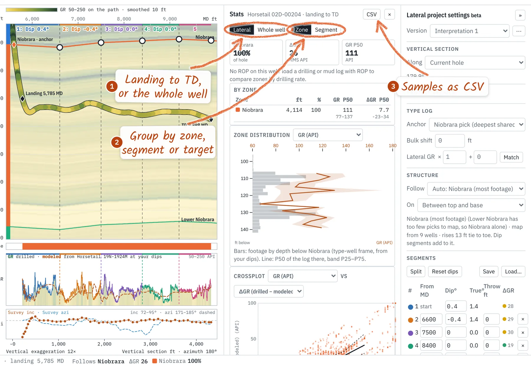
The Stats button (bar chart) opens footage, GR and ROP by zone, segment or target, from landing to TD or for the whole well; the zone distribution by depth below the reference top; crossplots and distributions of any two logs; and which logs move with ROP. Hover a point to find it on the section; CSV exports the samples.
14. Mouse and hot keys
- Right-click: options for what's under the pointer
- Shift-click: start a segment
- Drag ○: segment dip (Shift: every bed beyond)
- Drag ◆: move a pick (the anchor re-ties the beds)
- ↑ ↓: dip ±0.1° (Shift: 1°)
- Delete: remove the selected segment
- Wheel: zoom; over the type log, zoom it alone
- Shift-drag type log: bulk shift
- Shift-drag / Shift-wheel GR strip: shift / stretch GR
- Ctrl+Z: undo · Esc: close or cancel
- iPad: long-press for right-click; one finger pans or drags, two fingers zoom
15. Steering mode
The Steering panel tells a well being drilled from one already drilled (by default it is detected from the data: logs or surveys added in this project, or a LAS dated in the last 30 days; or set it under Mode). While steering, Project draws the path dashed past the last survey to the bit and Ahead of the bit: Hold the last station, Trend of the last N stations, or Constant curvature (DLS and toolface). The bit is each sensor's last reading plus its run's offset (Drilling → Runs and bit-to-sensor offsets). Only the path is projected, never a modeled log ahead of the bit. Retro wells show the bit readout without a projection.
- At the bit: the zone at the projected bit, ft below its top and above its base, TVD (TVDSS with a KB), the mean dip of the last N segments (N as in Trend) and ΔGR over the last 100 ft of log. While steering the status bar carries Bit: zone +below top / −above base.
- From plan: with an active plan, the distance at the last survey and at the bit, split high/low and left/right across the plan at its closest point, and 3D; the last stand's build, turn and DLS; and the constant DLS that meets the plan Back on plan in ft past that point (300 ft by default). No plan: one line says so.
- Aiming point: ft ahead of the bit (or a VS) along its azimuth, at a TVD or ft above the base of a zone in the interpretation. It gives the DLS of the arc to it, the inclination on arrival and the line-of-sight inclination, and draws a cross. Kept with the interpretation. Target lines with dip are not in yet.
- Call: target TVD and inclination (blank fields take the aiming point's) and a one-line reason. Log call adds it to the updates with the time and your name when signed in; Copy puts a call sheet on the clipboard. The updates list shows the last 3; Show all lists the rest.
- Handover: since the last 12 h, 24 h or the last handover: footage drilled (from dated surveys), surveys and LAS added, calls with their reasons, in-target and zone shares, the bit now and its projection, and your open questions. Copy or Email records the handover.
Calls and handovers are not drilling. Only surveys and logs added switch a well to steering.
Add a station takes one MD, inclination and azimuth (blank fields take the grey suggestion, the trend one course on). What-if (or Enter) draws it and projects on from it without touching the survey: chain several to ask where the bit lands if the trend holds, then Add all to survey or Clear what-ifs. Add to survey appends a station that didn't come through, after the dry run. Stations past the end of the log draw solid from the path's end; the log's last depth is marked Log end.
16. Additional features
- Continuous inclination (CINC). A near-bit inclination curve shapes the path between survey stations, corrected to pass through each station, with TVD by minimum curvature (Stockhausen and Lesso, SPE/IADC 79917). Right-click the Inc/Azi strip → TVD from.
- Azimuthal GR. Up GR in blue and down GR in red on the log strip, filled between them in the color of whichever reads hotter, and an up-minus-down strip in the same colors with ▾ where they cross: which way the bit is cutting the beds. Right-click the strip to choose the curves or turn either off.
- On the wellbore. Display → Section turns survey stations (dots), survey boxes (MD, inclination and azimuth), comments and the plan on or off; Reset all display settings brings them back.
- Directional plans. Drop a plan (MD, Inc, Azi, or targets in TVD or TVDSS with N/S and E/W): it is drawn dashed in the section, the mini map, the gun barrel and on the map, labeled plan. Every revision is kept; the well's ⚙ → Directional plans makes one active, hides or removes it. VS → Along plan lateral takes the plan's lateral azimuth.
- GR match. Lateral GR × … + … and Match level an MWD GR to the type log; the raw curve is unchanged.
- Survey review. Column mapping, north reference (grid or magnetic to true, with the declination or convergence worked out at the well), tie-in, rejected rows with reasons, Petrel deviation exports, and a dry run (append, merge, replace) before a re-load changes anything.
- Sidetracks. A lateral drilled out of a pilot or another wellbore: Sidetrack of (survey review or the well's ⚙) uses the parent's survey and tops above the kick-off, so TVD, tops and the steer are right from the heel. Each sidetrack keeps its own logs and interpretation; a survey that starts deep suggests the parent by API or name.
- Interpretation files. Export dip segments, horizons, tops crossed and position curves, plus a footage table; horizons and tops crossed carry latitude and longitude for any GIS or mapping package, and each horizon has a control column: crossed where the well crosses it in that segment, modeled where it comes from the type well, so mapping can weight or drop those points. All laterals packs every lateral you've opened here, one folder per well. Tick Without # header lines for packages that refuse them. Load… reads the interpretation back, along with horizons exported from other geosteering software and WITSML trajectories, logs and formation markers.
- Geosteering report. Export → Geosteering report, then Build the report. Customized report puts your company's logo and name on it (kept in this browser) and a client's (saved with the project); Well dates adds spud, landing and TD. One printable page: time in zone and target, footage by height above the target base (bin size in the report options), position, segments and the section, with survey stations and comments drawn on it and a comments table (each can be switched off). Survey table adds a page of stations. More than 8 segments continue on a second page.
Equations, defaults and limits: Methods.